- 您现在的位置:买卖IC网 > Sheet目录346 > NCP5021MUTXG (ON Semiconductor)IC WHITE LED DVR HV AMB 16-UQFN
�� �
�
NCP5021�
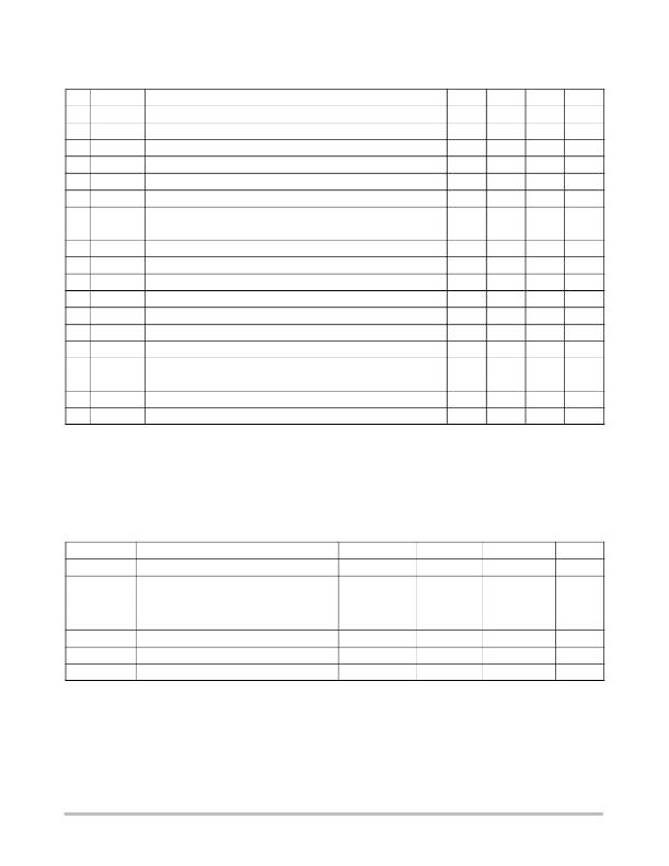
�Table� 4.� ANALOG� SECTION:� (Typical� values� are� referenced� to� Ta� =� +25� °� C,� Min� &� Max� values� are� referenced� ?� 40� °� C� to� +85� °� C� ambient�
�temperature,� unless� otherwise� noted),� operating� conditions� 2.85� V� <� Vbat� <� 5.5� V,� unless� otherwise� noted.�
�Pin�
�7�
�6�
�Symbol�
�I� REF�
�I� PK�
�Rating�
�Reference� Current� @� Vref� =� 1144� mV� (Note� 6)�
�Reference� Current� @� Vref� =� 1144� mV� (Note� 6)�
�Min�
�1.0�
�1.0�
�Typ�
�Max�
�100�
�100�
�Unit�
�m� A�
�m� A�
�k� ref�
�k� pk�
�Reference� Current� to� ILED� Peak� Current� Ratio�
�Reference� Current� to� Inductor� Peak� Current� Ratio�
�250�
�9700�
�7�
�6�
�9�
�9�
�4�
�V� REF�
�V� REFK�
�V� FB�
�M� DCY�
�I� LKGM�
�F� LF�
�V� VSD�
�Reference� Voltage� (Note� 6)�
�Reference� Voltage� (Note� 6)�
�Feedback� Voltage� (Note� 7)�
�Boost� Operating� Maximum� Duty� Cycle�
�Current� Mirror� Leakage� Current�
�Low� Frequency� Clock� derived� from� the� internal� 1.3� MHz� clock� (Note� 9)�
�Photo� Sense� Bias� Supply� @� Ibias� =� 1� mA�
�?� 3%�
�?� 10%�
�90.5�
�0.6�
�2.5�
�1144�
�1144�
�425�
�94�
�+3%�
�+10%�
�200�
�20�
�Vbat�
�mV�
�mV�
�mV�
�%�
�nA�
�Hz�
�V�
�4�
�4�
�5�
�R� VSD�
�I� SDUSD�
�G� AMB0.25�
�G� AMB0.50�
�G� AMB01�
�G� AMB02�
�G� AMB04�
�V� iph�
�Photo� Sense� Bias� Supply� internal� impedance�
�Photo� Sense� Leakage� Current� (Note� 9)�
�Photo� Sense� Internal� Gain� 1/4�
�Photo� Sense� Internal� Gain� 1/2�
�Photo� Sense� Internal� Gain� 1�
�Photo� Sense� Internal� Gain� 2�
�Photo� Sense� Internal� Gain� 4�
�Photo� Sense� Input� Voltage� (Note� 10)�
�30�
�0.25�
�0.5�
�1�
�2�
�4�
�100�
�1.5�
�W�
�nA�
�V�
�6.� The� external� circuit� must� not� force� the� I� REF� or� I� PK� pin� voltage� either� higher� or� lower� than� the� 1144� mV� specified.� The� reference� voltage� applies�
�to� both� IREF� and� IPK� pins.�
�7.� The� overall� output� current� tolerance� depends� upon� the� accuracy� of� the� external� resistor.� Using� 1%� or� better� resistor� is� recommended.�
�8.� This� parameter� guarantees� the� function� for� production� test� purposes.�
�9.� Guaranteed� by� design� and� characterized.�
�10.� The� ambient� sense� linearity� is� guaranteed� when� the� voltage� at� the� output� of� the� internal� amplifier� is� limited� to� 1.5� V.� This� voltage� is� equal� to� the�
�input� voltage� times� the� programmed� gain.� Beyond� this� value,� the� operational� amplifier� is� in� the� saturation� region� and� the� linearity� is� no� longer�
�guaranteed.�
�Table� 5.� DIGITAL� PARAMETERS� SECTION� (Typical� values� are� referenced� to� Ta� =� +25� °� C,� Min� &� Max� values� are� referenced� ?� 40� °� C�
�to +85� °� C ambient� temperature,� unless� otherwise� noted),� operating� conditions� 2.85� V� <� Vbat� <� 5.5� V,� unless� otherwise� noted.� (Note� 11)�
�Symbol�
�F� SCK�
�Rating�
�InputI2C� Clock� Frequency� (Note� 9)�
�Min�
�Typ�
�Max�
�400�
�Unit�
�kHz�
�V� IH�
�V� IL�
�C� IN�
�V� IHD�
�V� ILD�
�Positive� going� Input� High� Voltage� Threshold,� SCL,�
�SDA� signals�
�Negative� going� Input� High� Voltage� Threshold,� SCL,�
�SDA� signals�
�SDA� Input� Capacitance� (Note� 9)�
�I2C� Address� Extension�
�I2C� Address� Extension�
�1.6�
�0�
�Vbat� *� 0.7�
�0�
�10�
�V� BAT�
�0.4�
�15�
�Vbat� +� 0.3� V�
�0.3�
�V�
�V�
�pF�
�V�
�V�
�11.� Digital� inputs� undershoot� <� ?� 0.30� V� to� ground,� Digital� inputs� overshoot� <� 0.30� V� to� V� BAT�
�http://onsemi.com�
�5�
�发布紧急采购,3分钟左右您将得到回复。
相关PDF资料
NCP5050MTTXG
IC LED DRIVR PHOTO FLASH 10-WDFN
NCP5111DR2G
IC DRIVER HI/LOW SIDE HV 8-SOIC
NCP5304DR2G
IC DRIVER HI/LOW SIDE HV 8-SOIC
NCP5355DG
IC DRVR SYNC BUCK MOSF 12A 8SOIC
NCP5359ADR2G
IC MOSFET GATE DVR DUAL 8-SOIC
NCP5359DR2G
IC GATE DRIVER VR11.1/AMD 8-SOIC
NCP5360RMNR2G
IC DRIVER MOSFET 56QFN
NCP5366MNR2G
IC DRIVER MOSFET DFN
相关代理商/技术参数
NCP502ASQ15T1
制造商:ONSEMI 制造商全称:ON Semiconductor 功能描述:80 mA CMOS Low Iq Voltage Regulator in an SC70−5
NCP502ASQ15T1G
制造商:ONSEMI 制造商全称:ON Semiconductor 功能描述:80 mA CMOS Low Iq, Low−Dropout Voltage Regulator
NCP502ASQ18T1
制造商:ONSEMI 制造商全称:ON Semiconductor 功能描述:80 mA CMOS Low Iq Voltage Regulator in an SC70−5
NCP502ASQ18T1G
制造商:ONSEMI 制造商全称:ON Semiconductor 功能描述:80 mA CMOS Low Iq, Low−Dropout Voltage Regulator
NCP502ASQ25T1
制造商:ONSEMI 制造商全称:ON Semiconductor 功能描述:80 mA CMOS Low Iq Voltage Regulator in an SC70−5
NCP502ASQ25T1G
制造商:ONSEMI 制造商全称:ON Semiconductor 功能描述:80 mA CMOS Low Iq, Low−Dropout Voltage Regulator
NCP502ASQ27T1
制造商:ONSEMI 制造商全称:ON Semiconductor 功能描述:80 mA CMOS Low Iq Voltage Regulator in an SC70−5
NCP502ASQ27T1G
制造商:ONSEMI 制造商全称:ON Semiconductor 功能描述:80 mA CMOS Low Iq, Low−Dropout Voltage Regulator